|
|
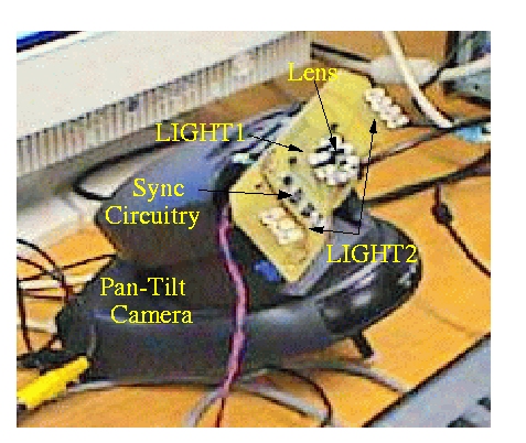
The light sources LIGHT1 and LIGHT2 in Figure 3 are composed of sets of 7 IR LEDs each. LIGHT2 is composed of two sets of LEDs, symmetrically placed on the left and right sides of the optical axis. Symmetry around the optical axis is desired because it reduces shadow artifacts by producing more uniform illumination, but asymmetrical configurations also perform adequately. LIGHT1 is placed near the camera's optical axis, so it generates the bright pupil image (Figure 2a) when it is on, and LIGHT2 is placed off-axis to generate a dark pupil image (Figure 2b), adjusted for similar brightness in the rest of the scene.
The video signal from the camera is composed of interlaced frames,
where
one frame can be decomposed into an even field and an odd field. Thus,
a field has half the vertical resolution of a frame. Let Ft
be an image frame taken at time instant t, with resolution c
columns (width) by r rows (height), or ![]() .
Ft
can be de-interlaced into Et and Ot,
where Et is the even field composed by the even rows
of Ft and Ot is the odd field composed
by the odd rows of Ft.
.
Ft
can be de-interlaced into Et and Ot,
where Et is the even field composed by the even rows
of Ft and Ot is the odd field composed
by the odd rows of Ft.
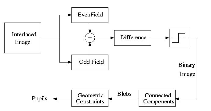
When LIGHT1 is synchronized with the even fields and LIGHT2 with the
odd fields, i.e., each illuminator stays on for just half the frame period,
one interlaced frame will contain both bright and dark pupil images. Figure
4 shows a block diagram of the pupil detection process. Once an interlaced
frame Ft is captured, it is de-interlaced and the odd
field Ot is subtracted from the even field Et
(dark from the bright pupil images). Thresholding of the difference image
then creates a binary image, which is the input of a connected component
labeling algorithm. Each connected component (blob) is checked for particular
geometric properties, such as size and aspect ratio, and those that satisfy
these constraints, are output as pupils. Observe that it is also possible
to detect pupils using (Ot, Et-1),
i.e., between frames, thus increasing the detection rate to 60 fields per
second.
|
|
The only piece of hardware build for the system was a very simple device
to keep the even and odd fields synchronized with LIGHT1 and LIGHT2 respectively.
Figure 5 shows a block diagram of the light synchronization device. The
video signal from the camera is received by a video decoder module that
separates the even and odd field signals. The video decoder is a National
LM1881 chip, that is mounted on the same board that supports the IR LEDs
(see Figure 4). The signal is fed to amplifying buffers that provide power
for the IR LEDs.
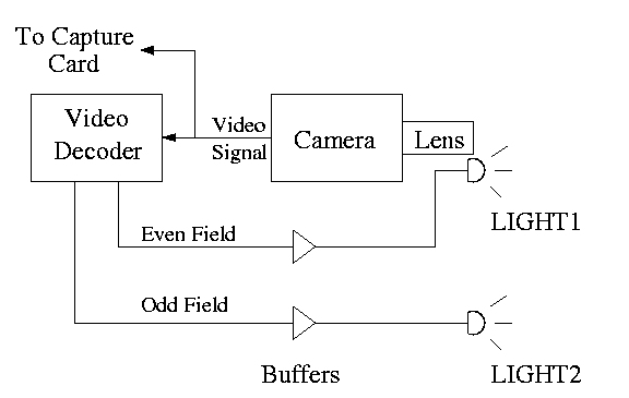
Figure 5: Synchronization device block diagram.